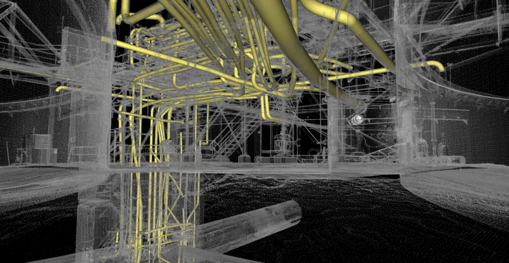
LiDAR Used to Create Digital Twins for Copper Mining

Digital twins enabled a more efficient return to full operation for an Arizona copper mining operation that needed to retrofit new industrial equipment into an existing, dormant processing mill. In the mining industry, restart procedures for a mill of this size are considered extremely complex and are estimated to take well over a year to complete.
The planned restart improvements and upgrades required precise measurements of existing facility conditions in order to create an accurate as-built digital twin of the mill. This digital twin was used for both clash detection and the installation plan of new equipment into the existing infrastructure.
A mega-project from start to finish, the overall size of the facility plus the volume of data points captured, demanded an organized, cohesive approach to ensure accurate deliverables to the client. Darling Geomatics scanned over 1 million square feet of this Arizona mine’s processing facility as well as over 4,000 linear feet of conveyors and roads over an eight day time period. Documenting the as-built structure accelerated the overall project timeline, eliminated clashes during new equipment installation, and provided a 3D digital record for future maintenance and operations.
Project Facts
Project: As-built digital twin of existing copper processing mill
Client: Copper mine
Project Location: Arizona, US
Industry: Mining
Application: As-built digital twin for planning and engineering
Technology Used: Ground-based LiDAR using various Leica 3D scanners and numerous CAD modeling software packages
Deliverable: As-built digital twin
Accuracy: +/- 6mm
Key Challenges
There were two primary challenges:
- Mega-project that included multiple structures, existing equipment, floor space, ductwork, conduit, and most of the external surrounding processing areas.
- Capturing all the required data points safely, without risking personnel.
Solution
“We worked at a mine in Arizona that had been closed for about 8 years. However, the current mining company is restarting operations with an estimated 20-year reserve of copper in the ground."
To successfully execute a project of this size, Darling Geomatics tackled this mega-project with three teams. The first Darling team scanned the exterior of the facilities and collected critical control points. The second Darling team scanned the grinding area and worked their way to the flotation building. The third Darling team scanned the concentrate thickeners, flotation building and finished with the tailings.
The Darling Geomatics teams used a total of four high-speed Leica LiDAR scanners. These scanners deliver excellent data quality and accuracies and are perfect for field work, being portable and quick to set up.
With LiDAR scanners, Darling was also able to scan and model the large overhead cranes that were adjacent to the roof of the flotation building — without having to climb up a ladder to get there. A great example of being able to capture required data without risking human safety.
Using this technology, Darling gathered billions of precise and accurate data points. In total, it took the Darling teams over 700 setups to successfully capture this volume of data.
All the data was registered in Leica Cyclone to produce the as-built digital twins that were needed for this project.
Summary
Darling Geomatics’ as-built digital twins were used for engineering purposes, providing future contractors with critical measurements and information necessary to complete the upgrades, retrofits and repairs required to successfully restart the mill.
One of the largest Darling projects to date, this mega-project of onsite scanning was completed in eight days with approximately three months of data processing, modeling, and analysis to complete the project. Using LiDAR technology, Darling Geomatics captured all necessary data without risking human safety, and delivered highly accurate data that was used to return this facility to full operations.


